Microphone preamp
It is widely known that the microphone amplifier in most sound cards has low sensitivity and poor frequency response. I do not mean USB microphones, which is a different story. Browsing consumer reports for various electret microphones one can be surprised that the same model is acceptable for some users and is absolutely inappropriate for others. I believe this is so not just because all people are different but also because the sound cards and microphones of various manufactures differ greatly in parameters. Actually, there is no single standard on the sensitivity of a microphone input of computer sound cards and the computer microphone response. This leads to a huge scattering of a microphone's behavior and one should be really lucky for a randomly chosen mic to work well with one's computer.
On top of this, most inexpensive ($3 - $15) electret computer microphones use very similar capsules and built-in FET (field effect transistor) preamps. They produce a voltage of 1-5 millivolts in normal conditions, while the sensitivity of the microphone input of sound cards is usually of the order of several dozens millivolts. Hence, in order for your voice to reach the computer software at an appropriate level one should either shout into the mic or chew it with one's lips. Is there any solution for this situation other than invest $$$ in a good quality mic and sound card? Sure - one can build a microphone amplifier.
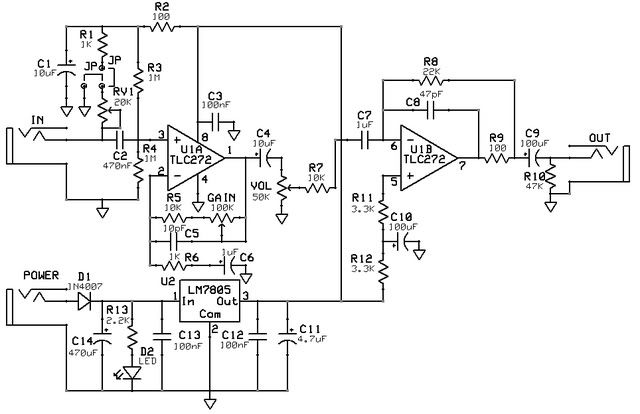
Just a one-transistor circuit shown to the left of the dotted line below does the job. I took as a prototype the one designed by Tomi Engdahl, see here for details. Instead of using the microphone input of the sound card one should plug it into a CD input of the motherboard, which has a way better frequency response and appropriate sensibility. One can also use the line input available on all sound cards. I use a Labtec Verse 524 electret microphone available for $5 - $10 online. I also tried a generic $3 "no-name" microphone which works practically as good as this one.

The noise level of this amp is mainly determined by the used transistor. I used a low-noise transistor KT3102E (the left one on the circuit) with parameter hFE = 650 manufactured in Russia just because I had it handy. A similar result can be obtained with internationally wide-spread low-noise transistors BC547B, or BC549, or their analogs. If a little noise is not a big problem, one can use a standard 2N2222, or 2N3904, or virtually any other silicon bipolar NPN transistor. The 51Ohm resistor in the emitter of the left transistor introduces a DC-feedback to improve the thermal stability of the unit. It is short-cut by an electrolytic capacitor to reduce the AC-feedback and increase the amplification. The 4.7K resistor is needed to provide the bias voltage for the mic's built-in FET. Two electrolytic capacitors connected to the mic compose a nonpolar capacitor. They can be replaced with just one. In this case the plus of the capacitor should be attached to a point at a higher potential chosen between the mic output and the base of the transistor. This depends on the used transistor and the mic which makes is difficult to predict. A direct voltage measurement with a high-impedance voltmeter is the easiest way to figure this out.
You will be amazed what this simple circuit can do. Although this is far from being a professional device, the captured voice quality is more than satisfactory. If I move 15' away from the mic it still is able to catch my voice. In real conditions I just place it in a corner of my desk ~3 feet from my head and speak normally as I would talk to somebody next to me. The mic works perfectly. The sound is very grasp and clear with no noticeable excessive noise. The QAMix mixer application (for ALSA on Linux) is used to set up the capture level from the CD input of my motherboard to 80%. One can drop it down in a noisy room and move the mic closer to oneself. The mic's sensitivity is somewhat higher than the one of the USB microphones built into the webcams. Here are my sample recordings with this preamp:
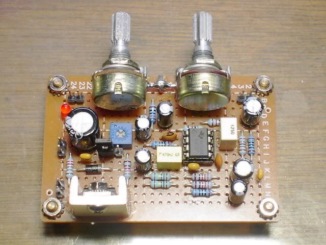
The circuit is mounted on a small board, the layout is straightforward. Actually, the picture below shows my first attempt at the preamp when I ran it from a 6V battery (4x AA cells). The design did not have the LF filter (the 150Ohm resistor and the large capacitor from the filter part are on the board). When I attempted to run this circuit from the +5V microphone connector on the motherboard, it turns out that it is not grounded to the chassis. In my design the ground connector of the mic jack has an electric contact with the chassis, while the CD input pins of the sound card are floating and not electrically connected with the chassis. So, I needed a power source grounded to the chassis. I tried to run the circuit from a +5V connector on the USB port which is definitely grounded. The circuit consumes less than 2mA of current and practically does not load the USB port, which can easily handle a 500mA load. However, this voltage is not filtered out good enough and there are ~10mV pulsations percolating through the preamp circuit to the CD input of the motherboard. This results in a noticeable 60Hz background humming. After adding the LF filter shown to the right from the dotted line the humming completely disappeared. You do not need this filter if you run the circuit from a battery.

Fig. 35: The preamp circuit board
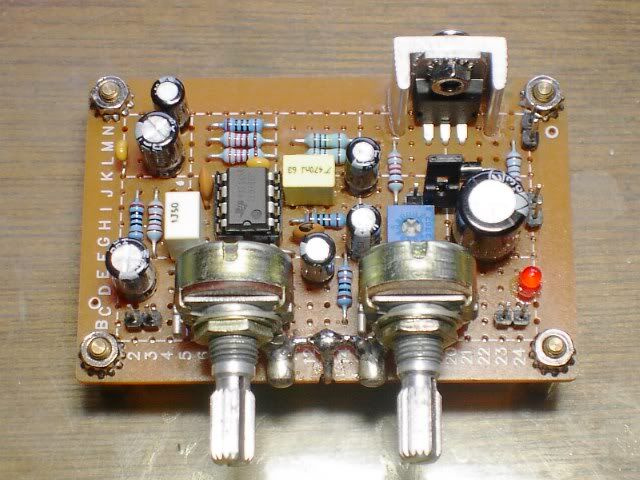
The board is mounted directly on the USB bracket. I drilled a hole for the 1/8" (3.5mm) microphone jack and fixed it on the bracket with the jack's nut. The board is very light and this mounting is pretty reliable. The jack and all other electronic components are available at RadioShack. One can use a similar approach to mount the board in a free bracket space of other PC extension cards.

Fig. 36: Mounting the board on the USB bracket
Here is a view of the board inside the PC. A longer than necessary blue cable connects it to the motherboard CD input. I just did not bother to shorten it out after the experiments. Since this is a mono-device, the left and right inputs of the CD connector should be short-cut. The red wavy wire is connected to the +5V pin of the on-board USB port. The LF filter elements are still not shown there. I added them later and mounted them on both sides of the circuit board. The layout is not very neat to display, next time I should be more careful in preliminary testing ;^)

Fig. 37: The board inside the computer case
The preamp works perfectly fine with Skype under Linux, my friends notice a good sound quality. Too bad that currently Skype for Linux software does not support video. Hopefully this will be fixed in future releases.